This component provides a mechanism for building workflows by interacting directly with a graphical representation of the workflow model.
This behaviour extends any previous behaviour, and all the abilities to interact with the model via the Advanced Model Explorer are still available. The original static graphical view is also available through the "Graphical" tab - this can be useful for providing more detailed views of the workflow such as viewing the bound ports.
New processors can be added to the workflow model by dragging from the available services panel directly onto the workflow canvas. The processor will assume the default name for that processor, but can be renamed by either double clicking and editing the name directly, or right-clicking and selecting "Rename".
You can also still add new processors to the workflow by dragging to the Advanced Model Explorer or right-clicking and selecting "Add to model", or "Add to model with name".
New inputs and outputs are added to the workflow by right-clicking a blank area of the diagram, and select "Create new Input ..." or "Create new Output ...". A dialogue box will then appear asking you to provide a name for the input or output - you must provide a unique name for this input or output.
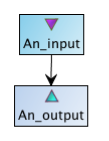
Once within the diagram, inputs and outputs can be distinguished from Processors by the small triangular icon that reflects the icon displayed in the Advanced Model Explorer. A small purple downward triangle denotes a workflow input, a small cyan upward arrow denotes a workflow output.
Processors ports can be connected together with data links in either direction. When right-clicking on a Processor element, there is a menu option "Select port ..." that provides access to both the processors inputs or outputs. Once selected a draggable arrow appears which may be dragged to the Processor you wish to link to. If the Processor under the cursor accepts this link the arrow will "snap" to the Processor box - at this point simply release the mouse and a liist of available ports to connect to will appear. Once the required port is selected the link will be made. This action can be cancelled at any point by clicking on blank area of the canvas.
To add a control link, right click on the Processor at the end of the link, select "Coordinate from ..." and then select the controlling Processor from the list.
Within the Interactive Diagram nested workflows are not represented in their expanded state, but instead as a single processor coloured pink. A view of the expanded state is, however, still avialable through the static Graphical view.
To edit a nested workflow, right-click on the nested workflow element and select the menu item "Edit Nested Workflow". This will open up the nested workflow in a new view allowing it to be manipulated just like any other workflow. The original parent workflow can be reselected via through the Taverna "Workflows" menu.

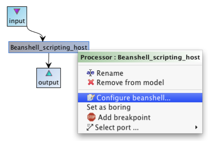
Processors that require additional configuration, such as Beanshell or Biomoby processors, can be configured by right-clicking and selecting the appropriate menu item. These configure options are identical to configuring a processor in the Advanced Model Explorer.
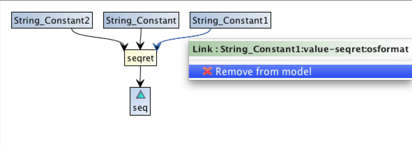
Workflow elements can be removed from the model by right clicking on that element, and selecting "Remove from model" - the title of the menu identifies the element that would be removed. This applies to Processors, Workflow ports, Data links and Control links. If a Processor or Workflow port is removed, any connecting links are also automatically removed from the model.